The Elecraft K2 moves its IF around based on which band, which mode, and which filter you have selected from its front panel. Each of those variations adds a little complexity to its setup in WriteLog’s SDR wizard.
The calibration procedure starts with WriteLog’s SDR offset screen set completely blank, like this:
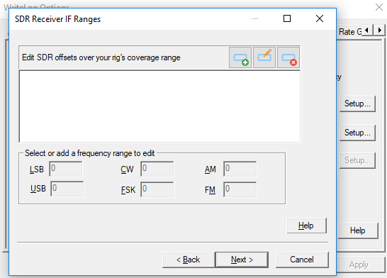
Click Next through the Finish of the wizard, and then “Run SDRS” and OK to set all the offsets to zero.
The objective of this exercise is to gather the necessary information about my K2 in order to correctly fill in the table on the SDR Receiver IF Ranges page above. The K2’s BFO and filter selection figures into the results. K2 owners already know those are set up in a calibration procedure done individually for each K2, so your K2 can and will have different settings than mine. But they will be reasonably close. The results also depend on what frequency your SDR is tuned to. In this example its a crystal controlled SoftRock Lite II with the 4.921 MHz crystal option. If you want to match my settings here as closely as possible, and have a tuneable SDR, then 4921 KHz is what you enter in WriteLog’s SDR on Receiver IF page.
The choice of band to start with is arbitrary, except that I happen to know that the Elecraft K2 tunes its IF in the opposite direction above 20MHz than it does below. That means we’ll end up with two bands on the Receiver IF Ranges page for this rig. The K2 doesn’t support AM or FM, so the bottom line is that we need 8 numbers to enter. 4 modes below 20MHz, and the same 4 modes above. Setup/SDRs Rates I have set for 96KHz coverage. Your choice does not affect this calibration procedure, but it will affect whether your screen matches mine. The full width of the SDR is shown here.
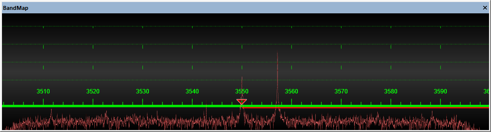
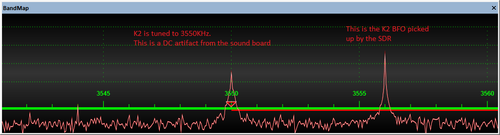
We’ll zoom into the frequency where the K2 is currently tuned, 3550KHz, for a close look at what we can see. The rig in this case is not connected to an antenna. That brings out artifacts that we won’t see when there is normal band noise in the IF. We can see the artifact produced by the combination of the SoftRock and sound card at the center of the SDR spectrum. And we can see the K2’s BFO, which leaks a little into the IF output jack I added to my K2.
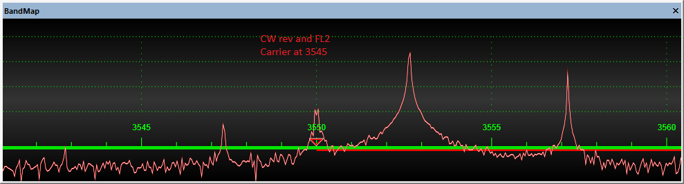
With the K2 in USB mode, and FL2, I put a few watts from a second rig into a dummy load at 3545KHz. Not one, but two blips appear on my Band Map.
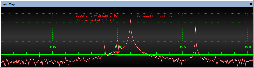
The second one is about 25dB down from the first, and notice it is exactly the same distance below the center of the SDR (at 3550) as the main carrier is above. That identifies the second blip as the result of an imbalance between the I and Q channels in my SDR/sound-board setup. It will be barely above the noise when I put an antenna on the the K2. (WriteLog’s Setup/SDR-Setup dialog has an Auto-Balance check box that will improve the image rejection a few dB.)
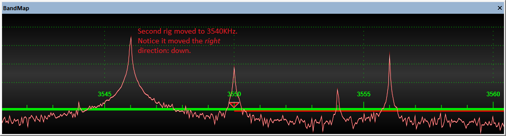
In order to know how to set WriteLog’s Flip I/Q bit, I temporarily move my second rig down the band by 5KHz and note that its blip moved in the correct direction. That means Flip I/Q stays off for this band.
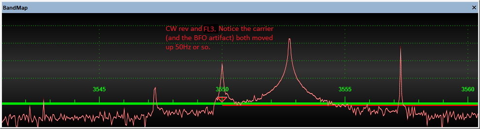
WriteLog cannot compensate for the shifts that occur when you switch receiver filters. We’ll check out how much they move, and chose a filter to be correct on the Band Map and measure its shift. Here is CW reverse, FL2:
Good news. Going to CW FL3 only moves 50Hz or so. The (incorrect) frequency readout for this measurement is the first one I want to keep for my WriteLog SDR setup table. The CW carrier appears at about 3552.8 (when the second rig is at 3545.)
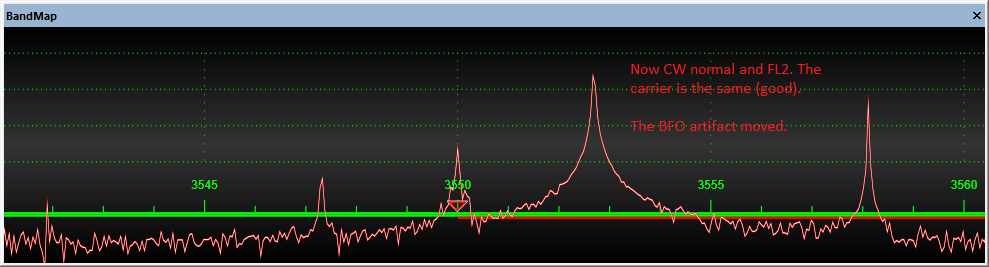
Switch to CW normal and the 3545 carrier remains in place (almost.) Its the BFO artifact that moved, and by nearly 1KHz.
Lets have a look at LSB. This number is another keeper. The blip is at about 3552.8 (while the second rig carrier remains at 3545.)
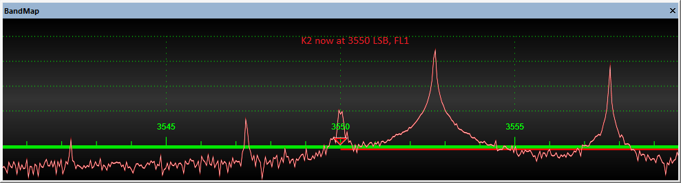
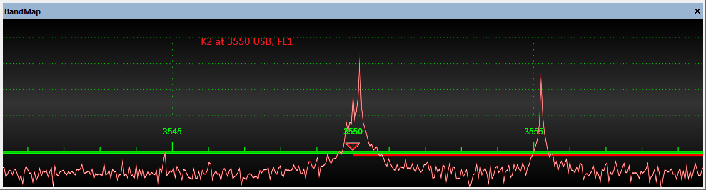
And USB using Filter 1. This is our USB number: 3550.1
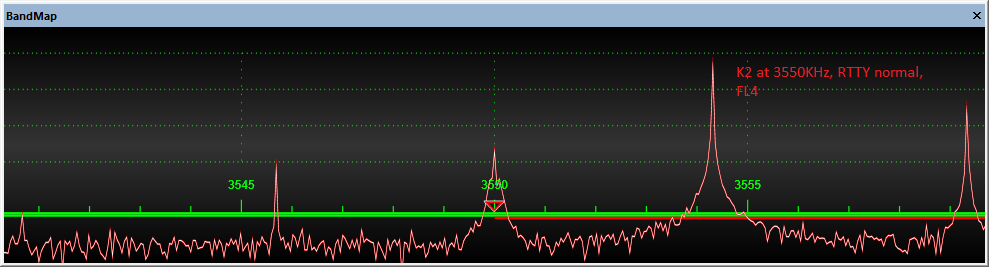
RTTY on FL4
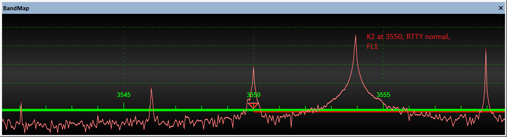
RTTY on FL1
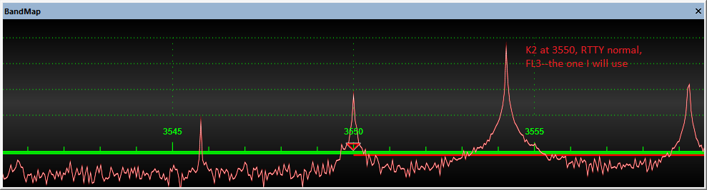
I have setup my K2 such that FL3 is my “normal” RTTY IF filter, therefore I’ll record this number for the table: 3554.2.
Now lets look at what happens on the K2 above 20MHz. I tune it to 21050, USB and with Filter 1. And I key down the second rig at 21055KHz. I chose 21055, by the way, because trying to imitate my 80m setup by using 21045 was off the zoomed-in screen. For my SDR table, I note for my SDR table that 21055 goes to 21052.9 KHz on USB.
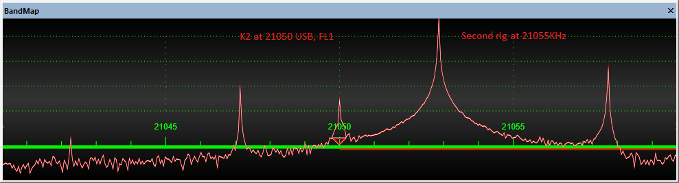
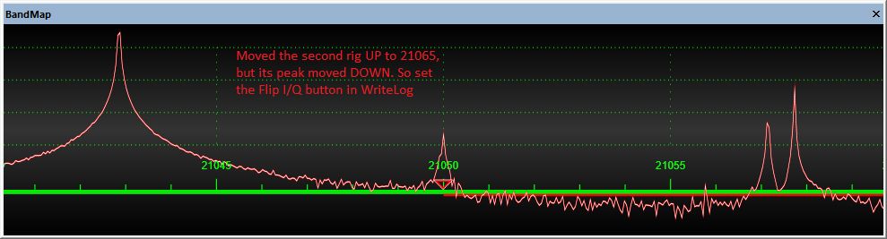
I expected this result from reading the K2 specifications. Its IF tunes backwards above 20MHz, so when I moved the second rig up 5KHz, its blip moved down instead. That requires setting WriteLog’s Flip I/Q button to compensate.
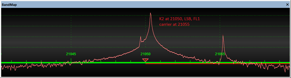
Go through the other modes. On LSB, FL1, 21055 goes to 21050.3.
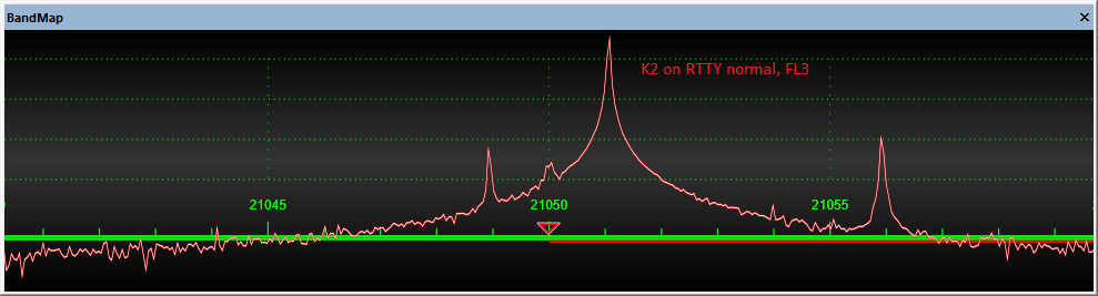
On RTTY FL3, 21065 goes to 21051.1 KHz.
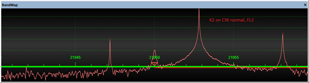
And CW, 21055 goes to 21052.9. By the way, I use CW normal above 20MHz on my K2 because it filters the same side of zero-beat as CW reverse does below. (The K2 has RTTY normal and reverse as well, but both stay on the same side of zero beat on all bands…I don’t know why the difference.)
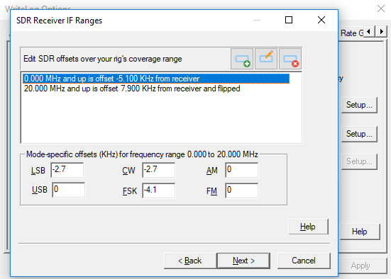
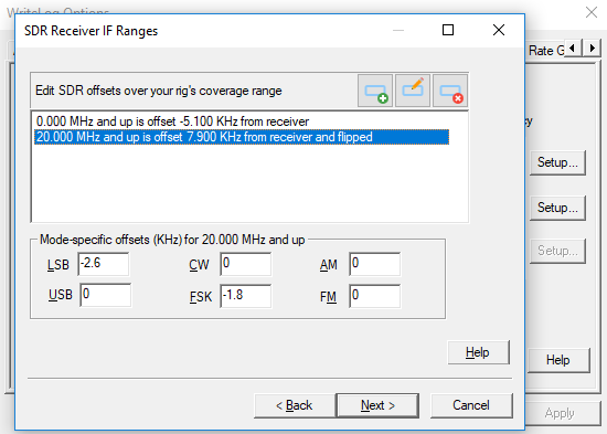
Now we have enough information to fill in the SDR table. The last two columns in this table are calculated and we’ll put them in the WriteLog SDR Setup. By the way, if you’ve skipped straight to this chart on the page, I remind you that this table only works with the equations below if you start out with WriteLog’s SDR Receiver IF Ranges page completely empty!
| Carrier Khz | K2 tuned | Mode | blip Khz | flipped | Band offset | Mode offset |
|---|---|---|---|---|---|---|
| 3545 | 3550 | USB | 3550.1 | no | -5.1 | 0 |
| 3545 | LSB | 3552.8 | -2.7 | |||
| 3545 | RTTY | 3554.2 | -4.1 | |||
| 3545 | CW | 3552.8 | -2.7 | |||
| 21055 | 21050 | USB | 21052.9 | flipped | +7.9 | 0 |
| 21055 | LSB | 21050.3 | -2.6 | |||
| 21055 | RTTY | 21051.1 | -1.8 | |||
| 21055 | CW | 21052.9 | 0 |
How did we get those last two columns?
First I arbitrarily defined the USB mode offset to be zero. Give that, then:
(for non-flipped bands)
Band_offset = carrier – USB_mode_blip
Mode_offset = USB_mode_blip – this_mode_blip
(for flipped bands)
Band_offset = (carrier – Rig_tuned) – (USB_mode_blip – Rig_tuned)
Mode_offset = this_mode_blip – USB_mode_blip
Enter that into WriteLog’s SDR setup until it looks like these two pages: