
Model MK-1100 Multi-Keyer
Availability
The MK-1100 multi-keyer is no longer in production. It is superceded by the MK-1101 and MK-1102 which are open-sourced hardware that you can build yourself.
Software support for them will continue in WriteLog.
Introduction
The MK-1100 multi-function keyer is a device that connects to your PC via a serial port and provides a variety of functions needed for a contest operation. It functions as a switch box for SO2R (single-operator, two-radio) contesters, but SO2R is not the only reason you might need a multi-keyer. All multi-keyer functions work on Windows 95, 98, Windows NT, Windows 2000, and Windows XP.
Front panel (prototype photo–production model has slightly different lettering):
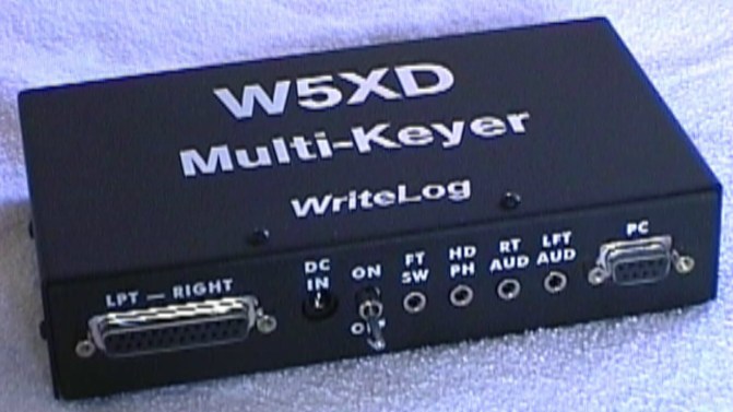
Back panel (prototype photo–production model has slightly different lettering):

Features
1. CW generation independent of the processor load on your PC running WriteLog. The “PC generates” CW option in WriteLog is vulnerable to timing disruptions caused by multi-tasking on your PC. If you run only WriteLog during your contesting operations, you probably won’t hear any CW timing problems, but some network drivers, CD writers, etc. have been known to multi-task poorly enough to affect WriteLog’s CW generation.
2. Separate opto-isolated CW outputs for a Left and a Right rig. WriteLog’s PC-generates CW function provides a single CW output plus a L/R output signal which requires an external relay to route separately to Left and Right rigs.
3. As an alternative to (2), the multi-function keyer provides separate TTL-level CW outputs on pin 17 of each of two LPT port connections if you already have LPT-to-CW cables compatible with other logging program CW outputs.
4. Separate opto-isolated PTT outputs for a Left and Right rig. The keyer’s PTT output can be configured in WriteLog specially for CW. For CW, it can be off (for QSK operation), or it can be programmed to insert a delay between PTT closure and the first CW character. If a PTT delay is selected it is imposed not only for PC-sent CW, but also for paddle-sent CW.
5. The PTT signals appear not only on the opto-isolated phone jacks, but also on pin 16 of the 25 pin D connectors for the antenna relay outputs.
6. The keyer has a footswitch input which causes a PTT closure for the current radio, Left or Right.
7. Paddle inputs for sending CW. Touching a paddle aborts any PC-generated CW in progress. WriteLog provides an INI file option to select your preference of the “automatic letter space” keyer mode. With the auto spacing turned ON, the paddle-sent CW extends any space between symbols that’s longer than a dot space to the 3 dot space inter-letter morse standard.
8. Antenna relay outputs separately for Left and Right rigs. The same pin out WriteLog supports on standard LPT ports for antenna relays is supported on the multi-function keyer.
9. Headphone audio switching. The audio relays in the multi-function keyer are controlled by WriteLog to match the 2 radio Entry Window in WriteLog according to the settings you have made in WriteLog’s Radio menu entries. The menu entries include both headphones connected to the active radio or one headphone to each radio. In either mode, there is a headphone latch menu entry that causes WriteLog to latch both headphones to the inactive radio until the transmission in progress finishes. When the transmission finishes, the headphones return to their previous setting (both ears on the active radio, or one ear on each radio). The multi-keyer’s receiver audio wiring is stereo, so rigs with sub-receivers are fully supported.
10. The Antenna relay, PTT, and CW outputs on the multi-function keyer LPT port outputs work on all current Windows operating systems: Windows 95/98/NT/2000. This keyer is the only supported way to obtain antenna relay outputs on Windows NT and Windows 2000. Because of parallel port driver limitations, WriteLog does not support the LPT ports on Windows NT/2000 PCs.
11. The multi-function keyer requires an RS-232 connection to your PC, but it can support all the above functions and rig control for one rig on just one serial port. Assuming you already were doing rig control on a serial port, then the multi-function keyer requires no additional ports on your PC.
12. The multi-function keyer generates a CW sidetone in the headphones for both Left/Right CW transmissions. The CwSidetonePaddles=NO in the Writelog.ini [configuration] section tells WriteLog to not generate a CW sidetone for PC-generated CW. CwSidetoneMachineSent=NO in the same section tells WriteLog not to generate a CW sidetone for machine-sent CW.
13. The keyer includes a speed control potentiometer and a SPST switch on a remoting cable to control CW speed and left/right radio switching manually without the PC running.
Includes:
- Keyer
- Remote speed and L/R switch box on 3 ft. cable
- Mating power connector (7.5V to 25VDC required).
Connections
There are three connections you must make to the multi-keyer, and there is one function you must use in order to use any of the other functions:
1. Power. The keyer requires between 7.5V and 25V DC at P9 in either polarity. The keyer draws about 100 mA.
2. You must connect RS-232 from your PC to the keyer connector labeled “PC”. Use WriteLog’s Setup Port… menu to indicate which COM port you are using on your PC. Version 10.10 or newer of WriteLog is required. In the same menu, select the W5XD multi+ keyer to the lower left.

At this point you can test whether the keyer is connected properly: after an OK to the Setup Ports dialog, look at the status line at the bottom of the main WriteLog screen. It should read out the keyer speed in WPM. Change the speed with Page up/Page down. If it says “timeout”, then step (1) or (2) is not correct yet. (It is possible to configure WriteLog to not have the status line at the bottom of the screen. Use the View menu to turn on the Status Bar check mark.)
If it says “timeout” you can confirm the power is connected OK by connecting the remote cw speed/left-right switch and toggle the L/R switch a few times. Listen for the relays in the keyer to switch.
3. You must use the multi-keyer to generate CW to enable the keyer’s other features. This means the only CW output will be from the CW L and R connectors on the keyer (or, alternatively) the TTL levels on pins 17 of the Antenna Relay 25 pin D connectors.
On the L/R connectors, the outputs are on stereo jacks with an isolated ground. The tip goes to your rig’s positive side, and the ring goes to your rig’s ground. The keyer ground should go nowhere.
4. You may connect CW paddles to the keyer.
5. You may connect receiver audio to Rec Aud L and R, which the keyer will route to HD PH for your headphones
6. You may connect a rig’s PC control port to the Rig connector. This way, a single COM port supports both PC control of a rig and control of the multi-keyer.
7. You may connect to the antenna relay, PTT, and/or CW outputs on Ant Relay separately for L and R rigs.
8. The keyer has a CW side tone circuit that can be disabled with internal jumpers, and whose pitch and other options can be controlled by INI file options from WriteLog.
9. The keyer comes with a small remote control box that has a CW speed knob and a manual Left/Right toggle switch. Both of these functions are operational even if WriteLog is not running.
All the above options are also described on WriteLog’s SO2R setup page, which has an especially useful schematic.
PTT Setup
The MK-1100 has both left radio and right radio PTT outputs, and for each radio, it has a TTL level on the 25 pin LPT jack, and a optically isolated on/off output in a mini stereo jack. The TTL output and the on/off output are internally connected to each other and have the same signal on them. And the keyer outputs either on the left or the right radio under control of WriteLog, which can be overridden by the manual toggle switch. The PTT and the CW output always go to the same radio.
Three different actions may cause the MK-1100 to turn on its PTT, and you may use WriteLog’s CW PTT Setup Dialog to set the keyer’s behavior:
1. If you activate the foot switch, the MK-1100 turns on PTT for as long as the foot switch is closed.
2. If you have the WriteLog CW PTT Setup dialog PTT Control configured for “LPT pin 16”, WriteLog will command the MK-1100 to turn on and turn off PTT on all of WriteLog’s CW transmission.
3. Also if you have “LPT pin 16” set, WriteLog sets up the MK-1100 to turn on its PTT when you do paddle inputs on the MK-1100.
There are two bugs in WriteLog prior to version 10.38 that affect the way you want to set this up:
1. Prior to 10.38, WriteLog would send the PTT command on CW transmissions regardless of the PTT Control setting in this dialog. In 10.38 and later, the MK-1100 obeys this dialog and sets PTT only if the “LPT pin 16” setting is on.
2. Prior to 10.38, the MK-1100 will not turn on PTT if you use paddle input unless you also set the PTT to CW delay non zero. 10.38 and later will command the MK-1100 to turn on PTT on paddle input if you set the PTT Control to “LPT pin 16” and will honor the zero delay setting.
Cable Documentation
The diagram shows the isolated ground wiring for the keyer’s PTT and CW outputs, which are on miniature stereo phone jacks.

Note that in many stations–especially for modern positive-keyed transceivers–the isolated ground available on the stereo CW output and PTT output jacks is not needed, and you can substitute a less expensive and off-the-shelf monophonic connector and cable assembly (a connector that has no “ring” contact) for the CW and for the PTT cables in your station.
Internal Adjustments
Inside the keyer are 4 dip switches and one volume control potentiometer.
Opening the case
1. Remove the eight black Phillips head sheet metal screws: 2 on top, 2 on each side, and 2 on the back. Do not remove the ninth screw which is on the bottom of the case.
2. Remove the 4 brass 3/16″ hex jack screws from the back panel: 2 each on the RIG connector and the ANT RLY – R. (Note: don’t confuse the back panel with the front; you need not remove any screws from the front panel in order to open the box.)
DIP SWITCHES
1. Side tone audio–Right headphone.
2. Side tone audio–Left headphone
3. Side tone audio ground
4. Self test. Leave OFF. The keyer will not operate with the self test switch ON.
The top three DIP switches can be turned off to disable the keyer’s side tone audio. The factory setting is ON. If you turn those top three switches off, then the keyer no longer shares a ground with your rig’s audio, which can be useful if you have a problem with an audio ground loop.
SIDE TONE VOLUME POTENTIOMETER
The potentiometer controls the volume of the CW side tone. The pitch of the side tone and other selections can be made in the writelog.ini file.
Paddle Logic
The paddle action is the standard iambic behavior: pressing the dot paddle sends dots, and the dash paddle sends dashes. The keyer implements dot/dash memories: at any time after a dot has begun, if the dash paddle is closed, the keyer “remembers” to send a dash after the dot. And the same for closing the dot paddle during a dash.
Adding another dot after the end of a dot requires holding the paddle down until the beginning of the second dot. And similarly for sending another dash after a dash: you must hold the paddle down until the second dash starts, else the keyer will only send the first one.
Circuit Diagram
At this time we do not have an electronic version of the Multi-Keyer circuit diagram. However, it is similar to the older design here:
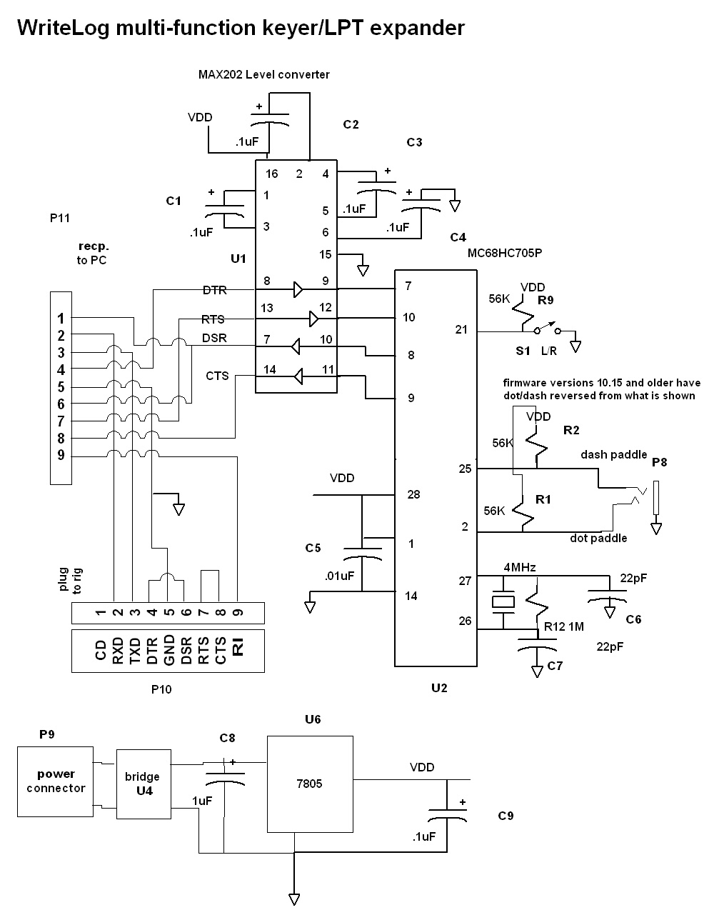
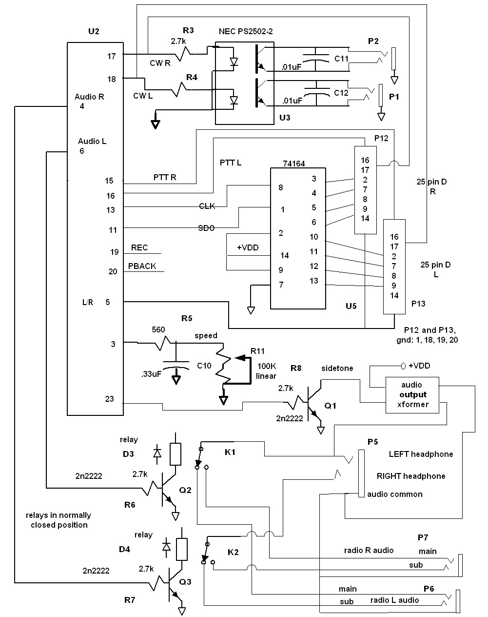
The new design adds opto-isolated PTT outputs, a foot switch input, and a self test switch.
MK-1100 Keyer Firmware
All MK-1100’s shipped had either version 10.26, 10.32 or 10.38 firmware.
Version 10.32 of the MK-1100 introduced two new features:
- Support for the Headphones Toggle functionThis command puts the headphones on the radio without the transmit focus (the “second” radio), or back on the transmit radio if they were already on the second radio.
- Support for the Radio Tune functionCommands CW key down until you type any key or press a paddle.
The keyer firmware version is printed on the label of the chip inside the keyer. It is not necessary to open the keyer to determine if you have the old 10.26 version of the firmware. Simply make sure your keyer is powered up and connected to WriteLog, and click WriteLog’s Radio menu entry. If the Headphones Toggle and the Tune entries are gray (disabled) then you have version 10.26 (or the keyer isn’t connected yet–can WriteLog send CW over the keyer? if so, it is connected).
Version 10.38 of the MK-1100 firmware introduced:
- Headphones unlatch works regardless of whether they are currently latched
- PTT off from the PC does not overide paddle input
Version 10.74 of the MK-1100 firmware was introduced after the MK-1100 ceased production. A limited number of upgrade chips were produced. Contact purchases@writelog.com for availability.
- PTT on command from the PC ignored while paddles are active. (Observed when auto-CQ is interrupted by paddle input. Subsequent time for auto-CQ would turn on PTT. Fixed in 10.74)
If your keyer has the older firmware, the keyer can be upgraded by ordering the part from WriteLog Contesting Software and installing it. The part is a 28 pin DIP integrated circuit that replaces the existing socketed part.
Example Software
The ability to set the RS-232 RTS/DTR outputs and read the CTS/DSR inputs is required in order to control the keyer. See the Programmer Resources page for the KeyerDemo.zip, containing some software routines in C++ that drive this keyer using the Win32 API.
This page updated 1 November, 2005