
There is increasing interest in implementing the ability to have an operator man an operating position at a contest station while not being physically present at the controls. The remoting is enabled by the presence of reliable broadband connections at both ends of the link: at the station where the rigs and antennas are (which I will call the remote site) and where the operator happens to be (which I will call the control site.) There is not an ideal or optimal implementation for this use. The design tradeoffs required are different for various remote sites and even each control site. There can be different solutions, each with its own compromises, and here is no optimal hardware nor software solution available.Each choice has its own costs (e.g. hardware to buy, cables to reconfigure, limitations on what can functions the control operator can invoke at the remote) and its own advantages. This post is a general discussion of what the parameters of the tradeoffs have to be for any remote control implementation.
Station not Remoted
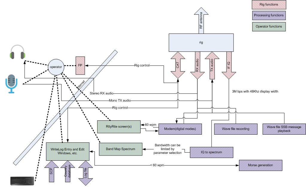
I start with picture of the station that is not yet configured to be remotely controlled, but will eventually be the remote site. Here is how it is set up to be operated for a contest by an operator physically present at the station.
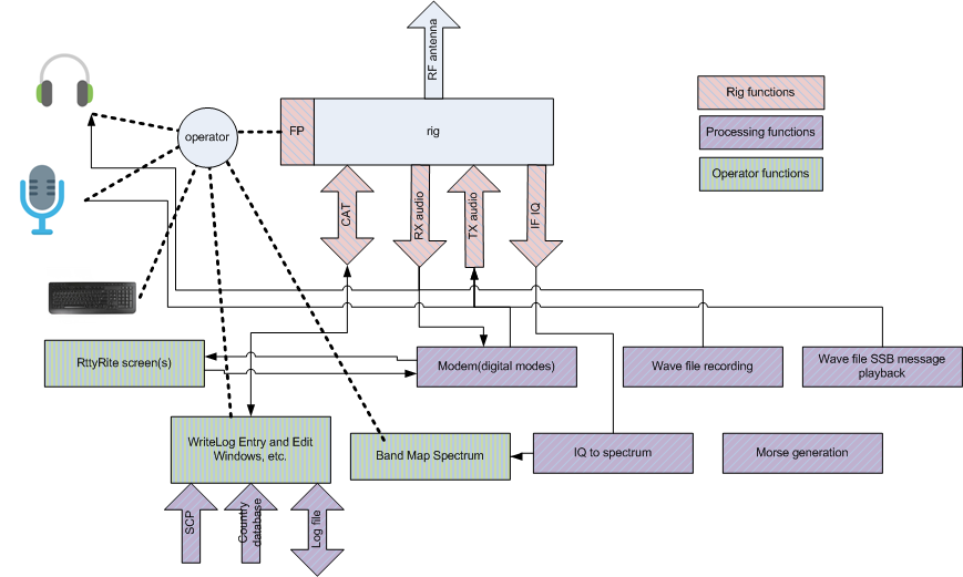
There is a radio (rig) being operated by an operator. I have taken the liberty to use the names of my own products, WriteLog and RttyRite, to illustrate what data must flow where, but other products would have to deal with the same data flow and constraints as are in this picture. While there are many different possible shack configurations, the usual case is that all the boxes labeled “Processing functions” as well as all those labeled “Operator functions” are deployed on a PC at the operator position that also has the keyboard attached. The microphone and headphones are local and, if not physically connected to the rig, are instead connected to the PC to be digitized and routed to/from the Rig’s mic and headphone connectors.
As we think about remoting the operator, note that the circle labeled “operator” and the rectangle labeled “Rig” are special because the functions they are linked to in the diagram must be available at the operator position, or Rig, respectively. (And that constraint is the major motivation for drawing this picture in this way.) The finer lines in the drawing are communications paths that are either inside the PC, or run on cables directly connected to the Rig. Those fine lines are where choices can be made for remote operation.
Optimal Use of the internet Connection
Now I ask the reader to bear with me as a jump to a rather complex conclusion and then work backwards for moment to justify it. Under the constraint that features available to the control operator will ultimately be limited by the latency and bandwidth of the internet connection, here is how the functions should be deployed across the two sites.
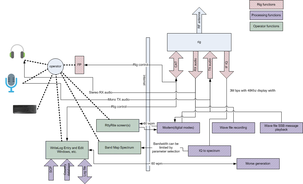
The optimal solution with respect to internet latency and bandwidth is that the logging program appears at the control site, where it has local access to super check files, country database, its saved log file, and the operator gets low-latency response from the RttyRite and the WriteLog displays. But all those rectangular Processing functions belong at the remote site. The RTTY modem, any wave file recording and SSB message wave file playback, IQ calculations (for a panadapter) and morse generation all need low latency, high bandwidth access to the functions attached to the rig, and all five of these provide a data compression on their operator side versus their rig side. Consider them in turn:
- The two wave file functions, recording and SSB message transmission are nearly perfect compressors. Almost nothing has to go across the internet for them to work.
- The RTTY (or any digital mode) modem uses audio bandwidth on its Rig side, but on the connection to RttyRite, only 60 wpm (or so) characters must flow across.
- CW generation requires very low latency at the Rig side, but can be controlled from the operator side using a relatively high latency link (e.g. WinKey)
- The spectrum display starts with an IQ stream in the Rig that is sampled at the same rate as the bandwidth planned to be displayed for the operator. For a 48KHz bandwidth spectrum display, there are two channels (the I and the Q) each sampled 48000 times per second and each sample is a 4 byte floating point number, and each of those bytes is 8 bits. Multiply all that out and the result is about 3 million bits per second. The spectrum on the operator side is computed using operator selected parameters and can be much smaller, depending on what update rate and spectral resolution is desired.
The connection to the rig front panel doesn’t appear in this discussion because I don’t know of any way it can be subdivided any further that the notion that the operator expects something like a front panel (with a display, knobs and switches), while the rig itself is at the remote. That is, it must be done and it doesn’t cost a lot on the internet anyway.
Analysis of RemoteRig
You can buy the hardware and software for RemoteRig today. It divides the functions this way:
Maybe the reader can correct me, but my general impression of the RemoteRig architecture is that it places everything except the rig itself and Morse generation at the control site. The IF IQ connection shows open in this configuration. I don’t think there is a way to get a spectrum at the operator site.
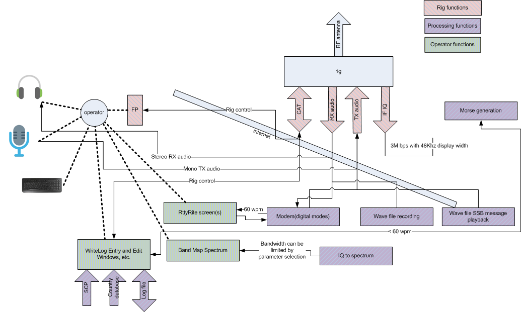
Analysis of FlexRadio SmartLink
FlexRadio sells the SmartLink solution. You must have a FlexRadio at the remote, and you must have a Windows PC and their SmartSDR product at the control site, and the result looks like this:
SmartLink has a panadapter at the control site and generates CW at the remote side. (I apologize for the internet shaped snake in the diagram. I just wasn’t willing to invest the energy to redraw it.) With WriteLog, in principle you could run a digital modem at the control site by setting up WriteLog’s DAX RX audio and DAX TX audio. (The last time I looked at SmartSDR and SmartLink, that combination did not provide DAX audio.) But I have to qualify my statement because the only sample rate available for DAX audio in both directions is 48KHz monophonic with 32 bit floating point samples. That puts a much bigger burden on the internet link than might be available.
WriteLog Remote Control Phase 1
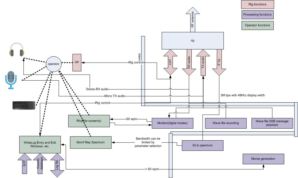
Here is my planned architecture for implementing remote control with WriteLog:
Its almost the logical opposite of RemoteRig. WriteLog puts everything except the front panel at the remote site.
The keyboard icon and the Operator functions are drawn such that they are across the internet from the operator. This is to depict the fact that WriteLog Remote Control (phase 1) plans on the use of TeamViewer (or other remote display/keyboard/mouse technology) to enable the control operator to manipulate WriteLog functions which are deployed only at the remote. Note that WriteLog itself is not deployed at all at the control site. The deployed software at the control site, besides the remote display, is the front panel interface. My current plan is to implement that with a special purpose hardware device, but, at least for test purposes, it would be possible to construct a software-only front panel interface for the control site. Its simply hard to do decent knobs and switches on a PC, even with a touch screen.
Thanks for this comparative analysis. It should greatly simplify the discussion. Initial comments:
1. No CW, PTT, FSK inputs shown. Is AFSK assumed? There needs to be CW from the logger as well as a paddle.
2. I like the format of leaving the block diagram the same in all scenarios, while drawing the Internet interface differently as appropriate. That makes comparisons obvious.
3. I have a K3/0-mini and would use that as my control location front panel. Will that work with your WriteLog scenario? I assume RemoteRig would be required to use the K3/0-mini as a front panel.
4. It would be helpful to summarize the benefit of the WriteLog scenario with the Internet drawn where it is on the diagram.
Ed W0YK
>1. No CW, PTT, FSK inputs shown. Is AFSK assumed? There needs to be CW from the logger as well as a paddle.
The purple “modem” box does FSK or AFSK. Thinking about FSK makes me realize my RemoteRig drawing needs another variation. RemoteRig has the ability to do FSK transmit over a remoted virtual COM port. So you get the “60wpm” bandwidth requirement on the transmit side, but the RX half of the modem lives on the operator side. That’s too much complication, I think, to diagram but I think words make the point?
“Morse generation” is for CW and its shown only connected to the logger. Paddle input is desirable and is not shown, and would be the same color and placement as the “FP” box. It is required at the operator position and puts constraints on the internet link. For paddles, the internet constraint is latency and not bandwidth.
> 3. I have a K3/0…
Yes, I believe RemoteRig only works if you have the manufacturer’s remote front panel hardware. My thinking for WriteLog is to neither help you nor hinder your use of the manufacturer’s remoting technology. I believe its possible to set up a remote virtual COM port, but special software is required for WriteLog (at the remote) and the K3/0 (at the control site) to both be able to access the rig concurrently.
>4. “benefit of the WriteLog scenario”
My purpose in this post was to try to be neutral to all the solutions except, obviously, the optimal one. But its a good question. In fact, it wasn’t until I drew all these diagrams that I realized that it is possible (over time) to implement the optimal scenario inside WriteLog AND get SO2R (which I am not sure can be easily had with the others?) The diagram makes it clear what WriteLog has to do and be. All the green and purple boxes already exist inside of WriteLog but not all of them can be split across the internet–not yet. Ham Radio Deluxe is not in my pictures (because its not really for contesting) but it already has the appropriate software architecture. You run a copy of HRD at both ends of a link the two cooperate with each doiing what is optimal its its own side of the link.
Wayne
Wayne, Thank you for your detailed thinking about the problems and possible solutions. The other solutions were cobbled-together and made to (barely) work and then bent to new purposes. This led to problems like no CW sidetone for the operator in SmartLink, or a thousand irrelevant settings in RemoteRig boxes. I think your thoughtful, careful approach has a good chance of providing useful capability. Best regards, Mark K6UFO